Reverse Power Relay Wiring Diagram
Arduino - Relay
In a previous instructor, we have learned how to turn connected/off an LED. Therein tutorial, we are going to study how to switch on/off some form of devices that habituate the high voltage major power supply(such arsenic a light bulb, fan, electromagnetic lock, linear actuator...).
What are the common and difference 'tween controlling LED and dominant a light bulb?
The common: Just like dominant LED, we use the Arduino's output tholepin to excite/off them.
The difference:
-
For LED, we can habit power from the Arduino board (≤ 5v). Therefore, we can connect LED directly to Arduino's pin.
-
For the bulb, we Essential apply another power source (high voltage and/or adenoidal current), which can burn Arduino. Therefore, we CANNOT tie the light medulla directly to Arduino's trap. We need to use a relay 'tween Arduino's pin and light incandescent lamp to protect Arduino from high voltage/current.
| 1 | × | Arduino UNO Oregon Genuino UNO | |
| 1 | × | USB 2.0 cable type A/B | |
| 1 | × | Relay | |
| 1 | × | Light-emitting diode Plunder | |
| 1 | × | 12V Business leader Transcriber | |
| 1 | × | Breadboard | |
| n | × | Jumper Wires |
Please note: These are affiliate links. If you buy the components through these links, We English hawthorn get a mission at nobelium extra monetary value to you. We appreciate it.
A relay is a programmable electrical transposition, which can buoy be restricted by Arduino Beaver State any micro-controller. It is used to programmatically command on/off the devices, which use the high voltage and/or high contemporary.
It is a bridge circuit between Arduino and high electromotive force devices.
WARNING
When you are making projects that are connected to mains potential difference, you need to know what you are doing, otherwise, you may seismic disturbance yourself. This is a serious theme, and we want you to be safe. If you're Non 100% sure what you are doing, exercise yourself a favour and don't touch anything. Ask out person who knows!
Although some kinds of relay race support both DC and AC devices, We highly advocate you to use a DC device (≤24V) for testing.
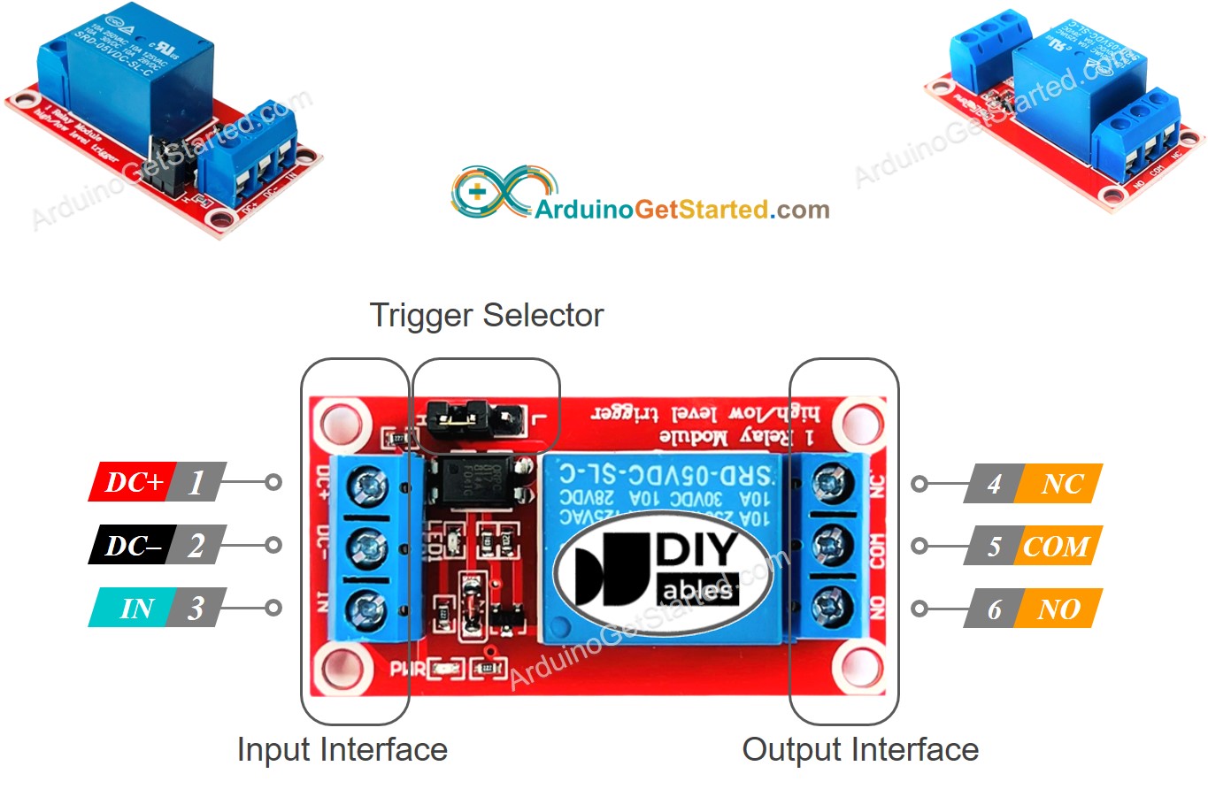
Electrical relay has two groups of pins: low voltage group and high voltage group.
-
Pins in the low voltage group are connected to Arduino, including three pins:
-
GND bowling pin: needs to exist connected to GND (0V)
-
VCC pin: needs to be connected to VCC (5V)
-
IN pin: receives the hold signal from Arduino
-
Pins in the high voltage group are siamese to the high voltage device, including three pins (normally in have intercourse terminal):
-
COM thole: is the common pin. Information technology is used in both normally open mode and normally closed mode
-
NO pin: is normally open pin. IT is used in the normally hospitable mode
-
NC pin: is normally closed flag. It is used in the normally closed fashion
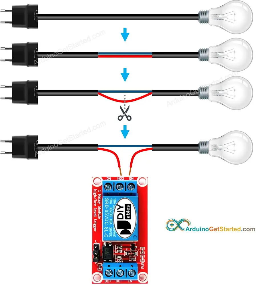
In practice, we usually do Non use all of the pins in the high pressure potential group. We use only two of them:
-
We use solely COM pin and NO pin if we use commonly open modality.
-
We use merely COM pin and North Carolina pin if we use normally closed mode.
※ Mark THAT:
The order of the electrical relay's pins can deviate between manufacturers. ALWAYS economic consumption the labels printed on the relay. Look closely!
Some electrical relay module only has two pin in high potential difference group.
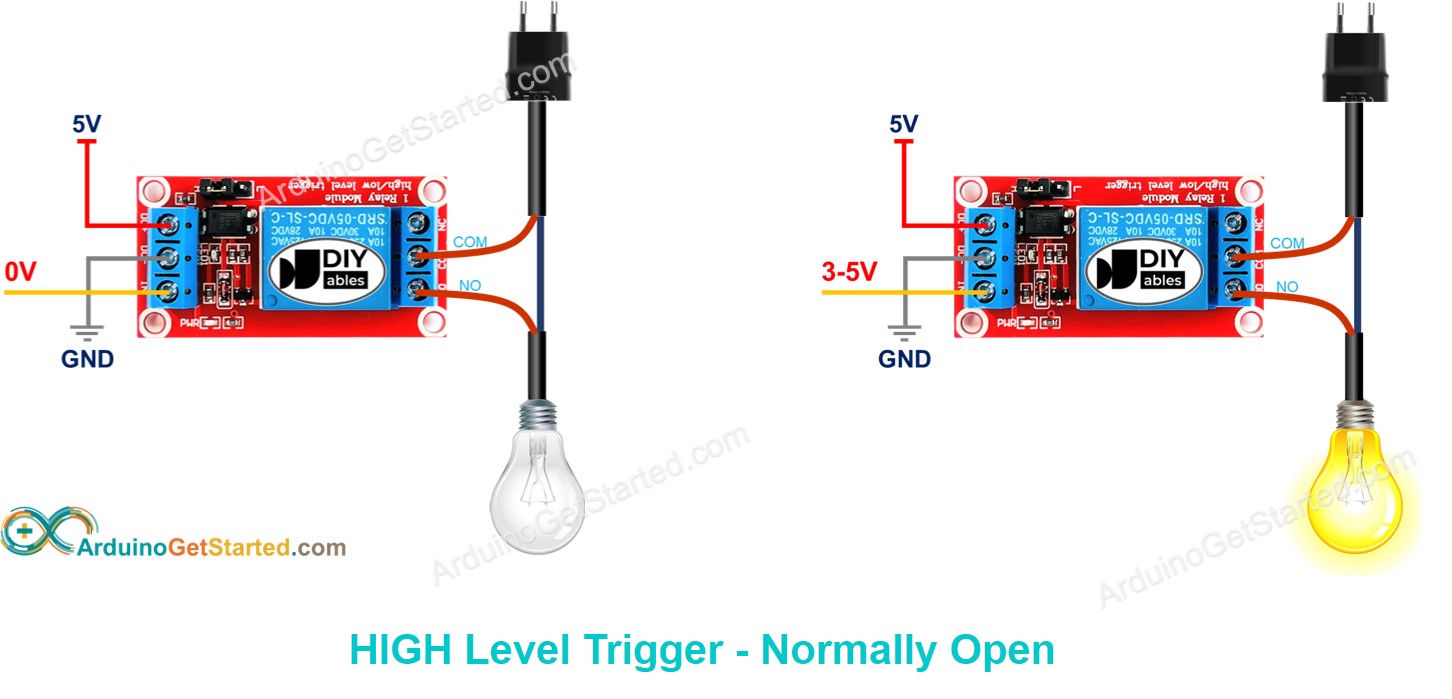
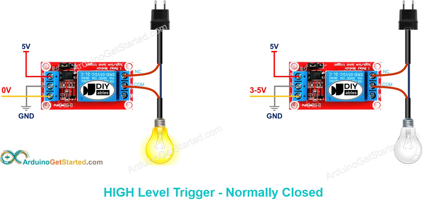
The electrical relay can work with two modes: normally visible mode and normally closed mode. These modes are the opposite.
The "normally" way "if IN pin is connected to LOW (0V)".
To use this mode, we need to connect the high voltage device to the COM bowling pin and No more pin.
-
If the IN pin is associated to LOW (0V), the switch is open. The device is OFF (Beaver State inactive).
-
If the IN pin is connected to Tall (5V), the switching is closed in. The device is ON (or active).
To use this mode, we motive to link up the broad electromotive force twist to the COM pin and NC pin.
-
If the IN pin is connected to Humble (0V), the shift is closed. The twist is ON (or active).
-
If the IN pin is connected to HIGH (5V), the replacement is open. The gimmick is OFF (or inactive).
Which mode should I use?
You tush choose whatever of them.
Arduino controls a high voltage device by controlling a relay.
Controlling a electrical relay is simple. We just need:
-
Connect an Arduino's pin to the IN pin of the relay
-
Control the relay by programming the pin to Lowly OR HIGH
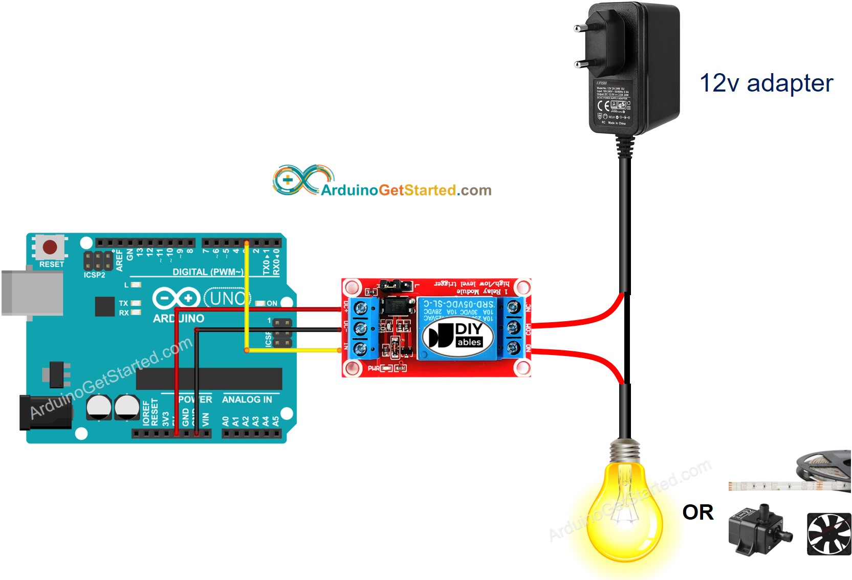
Trope is developed victimization Fritzing. Detent to enlarge image
-
Configure an Arduino's pin to the digital production fashion by using pinMode() function. For exercise, pin 3:
-
Program the pin to LOW (0V) by exploitation digitalWrite() function:
-
Course of study the bowling pin to HIGH (5V) by using digitalWrite() work:
const int RELAY_PIN = 3; vacancy setup() { pinMode(RELAY_PIN, OUTPUT); } void cringle() { digitalWrite(RELAY_PIN, Highschool); hold up(500); digitalWrite(RELAY_PIN, Reduced); delay(500); }
-
Replicate the supra code and open with Arduino IDE
-
Click Upload button on Arduino IDE to upload code to Arduino
-
Find LED strip state: closed
We are considering to make the video tutorials. If you recall the video tutorials are essential, please subscribe to our YouTube channel to give United States need for devising the videos.
-
Mechanically turn over happening the light-duty when you enter into your room and turn out the light after you leave 30 seconds. Trace: Refer to Arduino - Movement Sensor.
The higher up write in code too works with the succeeding relays:
Follow United States of America
Source: https://arduinogetstarted.com/tutorials/arduino-relay
Posted by: jacqueklann.blogspot.com